Compool Cp3810 Instructions d'exploitation
Naviguer en ligne ou télécharger Instructions d'exploitation pour Accessoires pour piscines hors sol Compool Cp3810. Compool Cp3810 Operating instructions Manuel d'utilisatio
- Page / 43
- Table des matières
- MARQUE LIVRES
- Cp3810 AQUATIC CONTROL SYSTEM 1
- Table of Contents 3
- Compool Cp3810 4
- Safety Notice 5
- Introduction 6
- Plumbing Requirements 8
- Installation 10
- SUB-PANEL 11
- TO LIGHT 13
- PART# PC-LX3810COMPOOL 11099 14
- WATER SENSOR 16
- FREEZE SENSOR 16
- System Options 19
- ACTUATORS 21
- CONTROL JUMPER 21
- AUXILIARY VALVE 21
- SOLAR SENSOR 22
- FREEZE I/L SYST 25
- SPEC FUNCT 25
- System Start-up 26
- Operating Instructions 27
- Programming 30
- Calibration 33
- Power Center 35
- Spa-side Remote 36
- Problem Solving 39
- Compool Cp 3810 41
Résumé du contenu
CompoolCp3810 AQUATIC CONTROL SYSTEMInstallation & Operating Instructions04/23/97941-1100
8Compool Cp3810InstallationHigh Voltage WiringPower Center with built in Sub-panelAt the equipment pad, mount the Power Center within 15’ of all the e
9Compool Cp3810System PowerSystem Power provides power to the transformer.• To wire System Power1. At the Sub-panel, install a circuit breaker for Sys
10Compool Cp3810Equipment PowerThe diagram above shows how the filter pump is wired. Additional pumps should be wired the same way. • To wire high v
11Compool Cp3810Underwater LightsHigh voltage pool/spa lights require GFCI protection. To meet electrical code requirements, the pool/spa light must
12Compool Cp3810Low Voltage WiringPower Center Circuit Board 12ONWATER SENSORREDGRNREDGRNSELECT 4 CIRCUITSORGREDYELGRNBLUBLKSwitch 1Switch 2Switch 3Sw
13Compool Cp3810Low Voltage CablesControl Panel6-conductor cable runs between the Control Panel and the Power Center. Heater Connection2-conductor ca
14Compool Cp3810Water Temperature SensorThe Water Temperature Sensor measures pool and spa temperature.• To wire the Water Temperature Sensor1. Select
15Compool Cp3810making connections, cut off stripped ends of cable. Insert the 2 wires to be connected into the connector and squeeze the connector
16Compool Cp3810Modular Crimping ToolThe Crimping Tool is required to attach modular connectors to the Hookup Cable. The tool may be purchased from a
17Compool Cp3810System OptionsSpa-side Remote The Spa-side Remote is typically installed in the tile-line of the spa. See Plumbing Requirements for d
18Compool Cp3810REM1 Activates AUX1 equipment.REM2 Activates AUX2 equipment.REM3 Activates AUX3 equipmentREM4 Activates AUX4 equipment.REM5 Activates
19Compool Cp3810Note To control more than three Valve Actuators, see Valve Module for details.Valve ModuleThe Valve Module (model MOD-VLV3) allows th
20Compool Cp3810Solar HeatingSolar systems require the following additional equipment, a Solar Temperature Sensor (model TS-5L), a Valve Actuator (mod
21Compool Cp3810during these conditions, it is necessary to adjust the HI SPD program switch, which is located at bottom of the Power Center circuit b
22Compool Cp38104. Program the backwash interval and duration times at the Control Panel. See Calibration for details. Floor Cleaner Valve The Floor
23Compool Cp3810Configuration SwitchesAfter setting configuration switches, turn system power off for a few seconds.FREEZEFreeze settings are used to
24Compool Cp3810HIGH Activate high speed when spa or pool is on.HTR Activate high speed when heater is on.AUX1 Activate high speed when AUX1 is on.
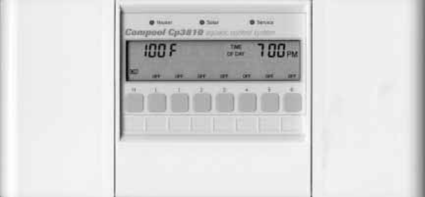
25Compool Cp3810Operating InstructionsControl PanelInstalled at a convenient location inside the house, the Control Panel provides complete control of
26Compool Cp3810A solid OFF indicates the equipment is off.A blinking ON indicates the cleaner is in a safety delay mode. The cleaner will turn on
27Compool Cp3810Temperature ControlLocated behind the left door of the Control Panel is the Temperature Control area. Heating choices are selected us
1Compool Cp3810Table of ContentsSafety Notice. . . . . . . . . . . . . . . . . . . . . . . . . . . . . . . . . . . . . . . . . . . . . . . . . . . . .
28Compool Cp3810Fahrenheit/Celsius keyLocated behind the right-door of the Control Panel is the Temp. Display key. Press this key to select Fahrenhei
29Compool Cp3810ProgrammingTypically only the L key (filtration) needs to be programmed. Other Equipment keys can be programmed the same way.• To pro
30Compool Cp3810Follow Programming example, set START TIME to 0:00 hours. Set RUN TIME to the number of Hour/Minutes before equipment should Time-out
31Compool Cp3810CalibrationThe temperature sensors, backwash, and floor cleaner valve can be adjusted in the calibration mode. Allow pool to run 5 mi
32Compool Cp3810Note Solar, backwash, and floor cleaner valve adjustments are skipped if feature is not enabled. Tips for calibrating the temperatur
33Compool Cp3810Power CenterEquipment keysLocated at the equipment pad, the Power Center provides manual-override capability of your equipment. Cautio
34Compool Cp3810The P key turns on the Filter Pump.Keys 1-6 activate auxiliary equipment.Activates the Heater and Solar.3 - Hour Filter OverrideIt is
35Compool Cp3810To activate the Heat Boost, press the designated button. The light will blink during the 5-minute cycle to indicate that the spa is b
36Compool Cp3810System OptionsTelephone ModuleThe Telephone Module allows controlling the spa or pool with a phone. To operate from inside the home, p
37Compool Cp3810Problem SolvingDisplay shows “Err 1”If there is a fault with the Water Temperature Sensor, the display will show “Err 1”.Check sensor
2Compool Cp3810Operating Instructions. . . . . . . . . . . . . . . . . . . . . . . . . . . . . . . . . . . . . . . . . . . . . . . . . . . . 25Control
38Compool Cp3810Heat Source does not allow SolarAt the Power Center circuit board, the SPEC FNCT configuration switch SOLR needs to be turned on. Se
39Compool Cp 3810
40Compool Cp3810Index2-speed Filter Pump Control 363 - Hour Filter Override 34Adding Relays 10Backwash Control 21Calibration 31Canceling Heater and Cl
41Compool Cp3810Problem Solving 37Programming 28Programming 29Programming a Once-only 30Programming a Time-out 29Programming additional Run Times 29Re
3Compool Cp3810Safety NoticeImportant Safety InstructionsWhen installing and using this electrical equipment, basic safety precautions should always b
4Compool Cp3810IntroductionPackage ContentsThe CP3810/S system includes the following components.CP-3810 Control Panel (w/ cable) (1 qty.).LX-3810 Pow
5Compool Cp3810The CP3810/SL system includes the following components.CP-3810 Control Panel (w/ cable) (1 qty.).LX-3810L Power Center (1 qty.).SNS-KIT
6Compool Cp3810Plumbing RequirementsCONTROL PANELPOWER CENTERSOLARSENSORCLEANERPUMPCVA-24HEATERCVA-24SOLARPUMPVACUUMRELIEFWATERSENSORSKIMMERFILTERPUMP
7Compool Cp3810Plumb system in accordance with recommended hydraulic schematic.1. If a Spa-side Remote is to be used, install a 3” to 6” length of 1.5
© 2020, manymanuals.fr. Tous droits réservés | 5.611 s |
 Manymanuals.com
 Manymanuals.de
 Manymanuals.fr
 Manymanuals.it
 Manymanuals.pl
 Manymanuals.cz
 Manymanuals.es
 Manymanuals-pt.com
Commentaires sur ces manuels